From: DPW-6 <aiaadpw@gmail.com>
Subject: AIAA 6th CFD Drag Prediction Workshop: Abstracts, Geometry Issue
Date: April 10, 2016
Dear DPW-6 Participants,
we would like to point out two aspects:
- abstract
- geometry wing leading edge tangency issue
1. Abstract:
for our planning and the announcement at the conference we would like to ask for a very short abstract presenting the title of your presentation, the authors and their affiliation.
Please, could you send this, maximum ½ page, to us by 31st April if you do not have send already an abstract?
2. DPW-6 Wing Leading Edge Tangency Issue:
- Thanks to Benedikt Koenig from Exa for contacting us regarding a tangency issues with the DPW-6 wing leading edge geometry.
- The DPW-6 committee started some investigations and has come to the following summary:
- The surfaces defining the NASA CRM wing are split at the leading edge with no tangency constraint.
- Although typical wing aero design processes may do this differently, the NASA CRM wind tunnel model was built as defined by the IGES files used in DPW-4, which include the split at the wing leading edge.
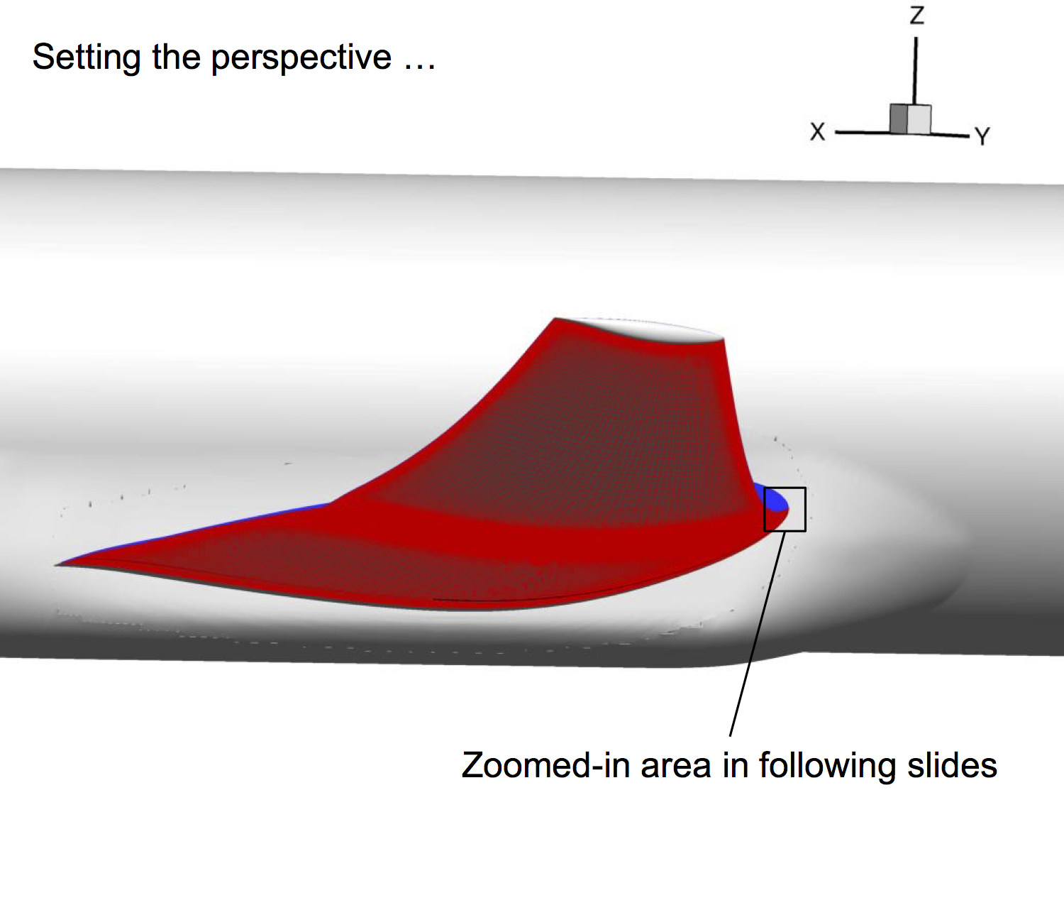
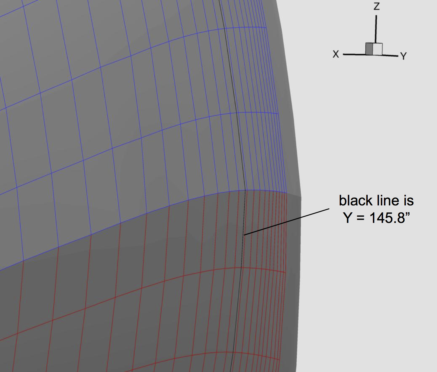
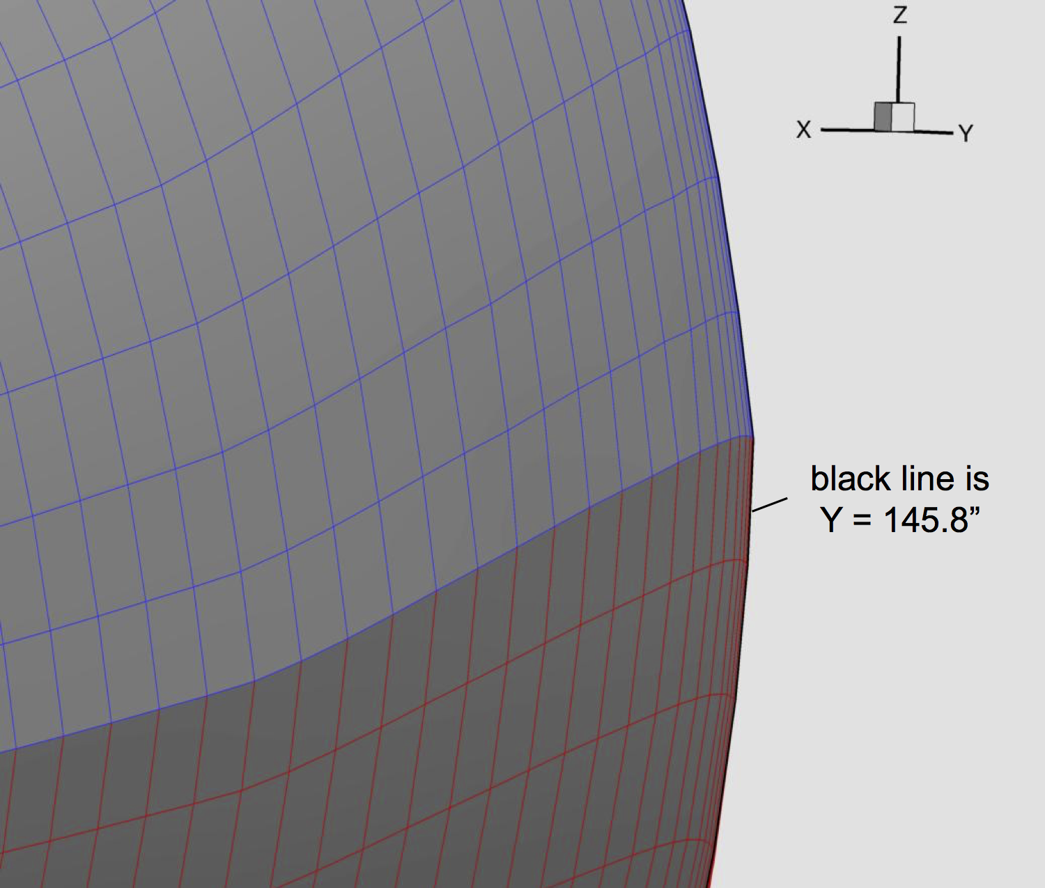
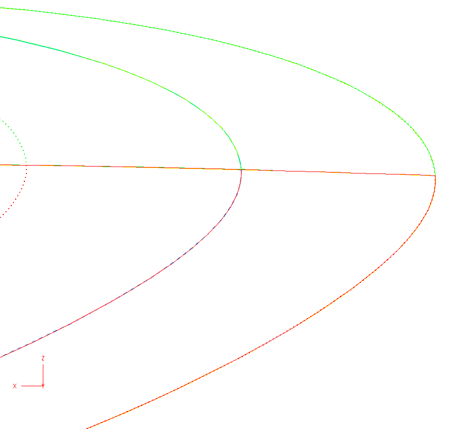
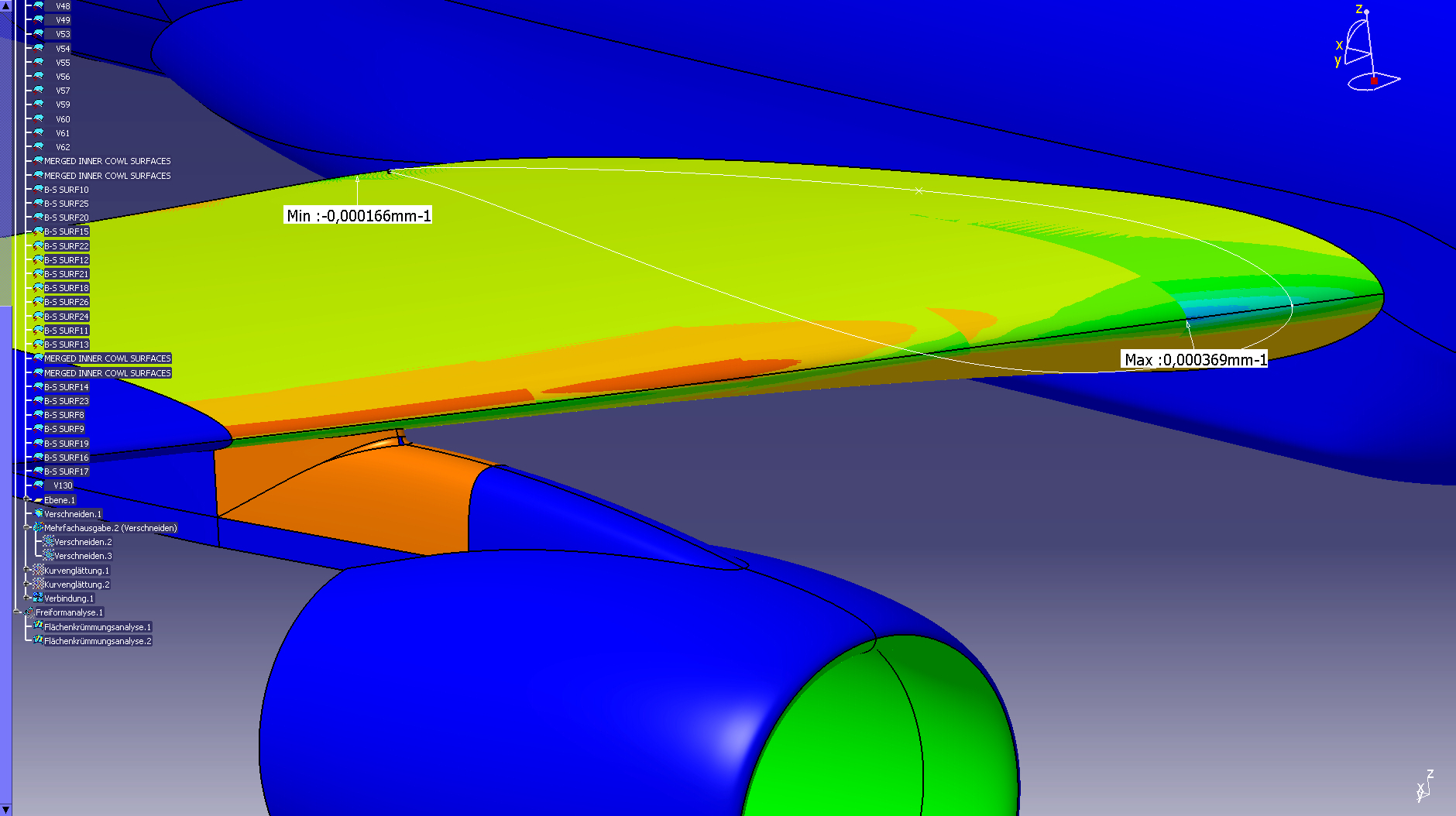
- The attached figures 'crm_initial....jpg' show Gaussian curvature on the inboard wing of the DPW6 geometry. The edge angle measured near the wing root at y=145.8 inches is about 6.58deg for the undeformed, and 6.82deg for the "ae4.00deg" geometry. This implies that the tangency issue was not induced by the geometry deformation procedure.
- DPW4/DPW5 have a very small tangency difference, but the DPW6 tangency discontinuity is notably larger than the previous DPW files in sections of the surface away from defining knots.
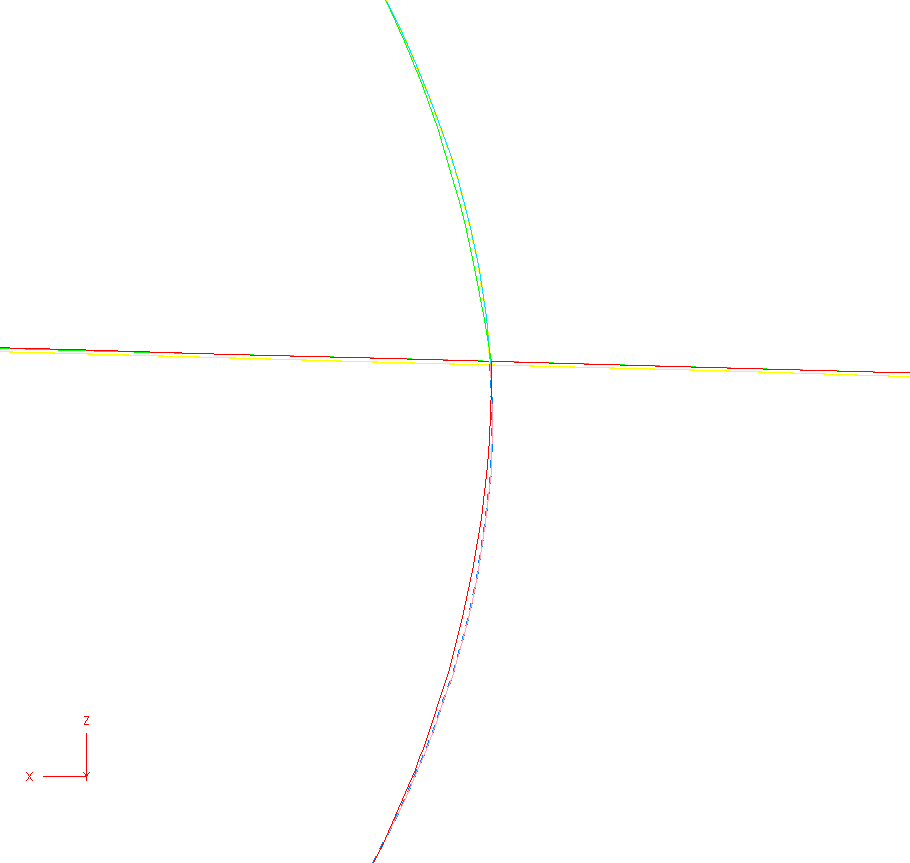
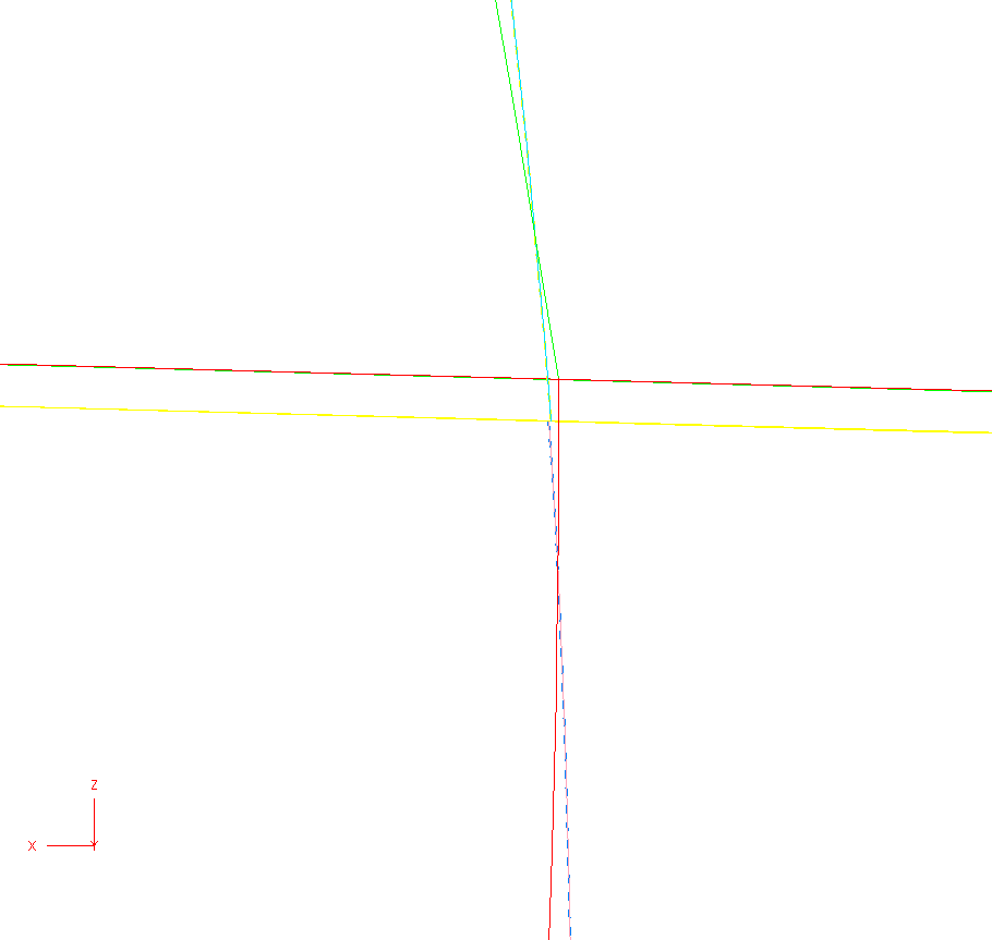
- In addition, the location of the split varies between the defining sections, compared to the DPW4/DPW5 geometries (see attached files, y145p8_view…png)
o thick dotted lines are the defining knots
o thick solid lines in the middle is a cut at y=145.8, essentially midway between defining knot sets
o view2, view3 (zoomed in on the intersection curves):
o DPW4: blue/yellow dashed line
o DPW4: pink/cyan solid line
o DPW6 (ae2.50): Red/Green thick line
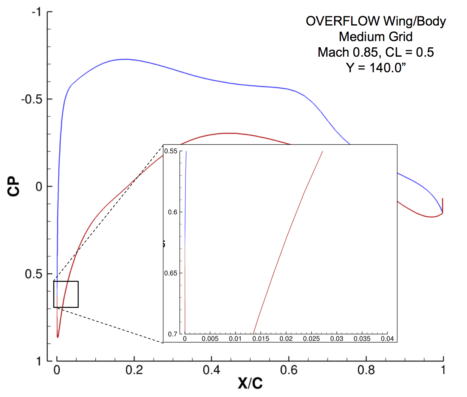
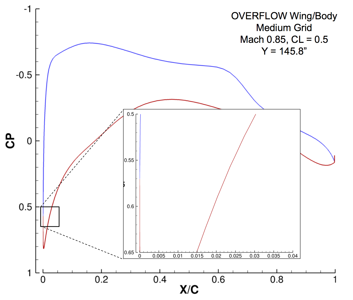
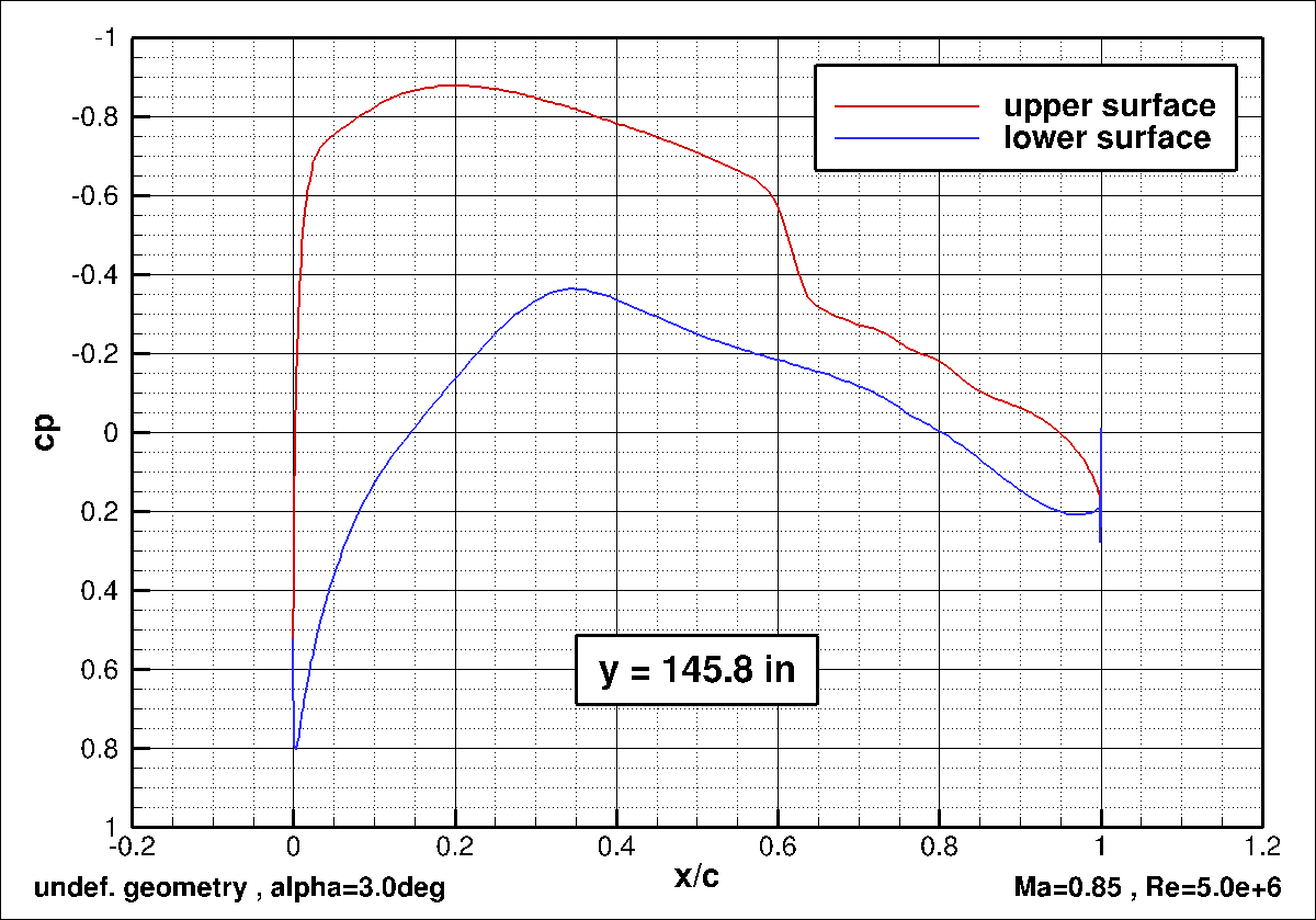
- The good news: the attached plots of chordwise cp for OVERFLOW and TAU solutions at the above spanwise position do not show cp perturbations caused by the discontinuity between the upper and lower surface, although the stagnation point is on the lower surface. This was checked for the medium OVERFLOW & TAU-Solar grids/solutions and for ultra-fine OVERFLOW grid.
Kind regards
The DPW-6 Committee