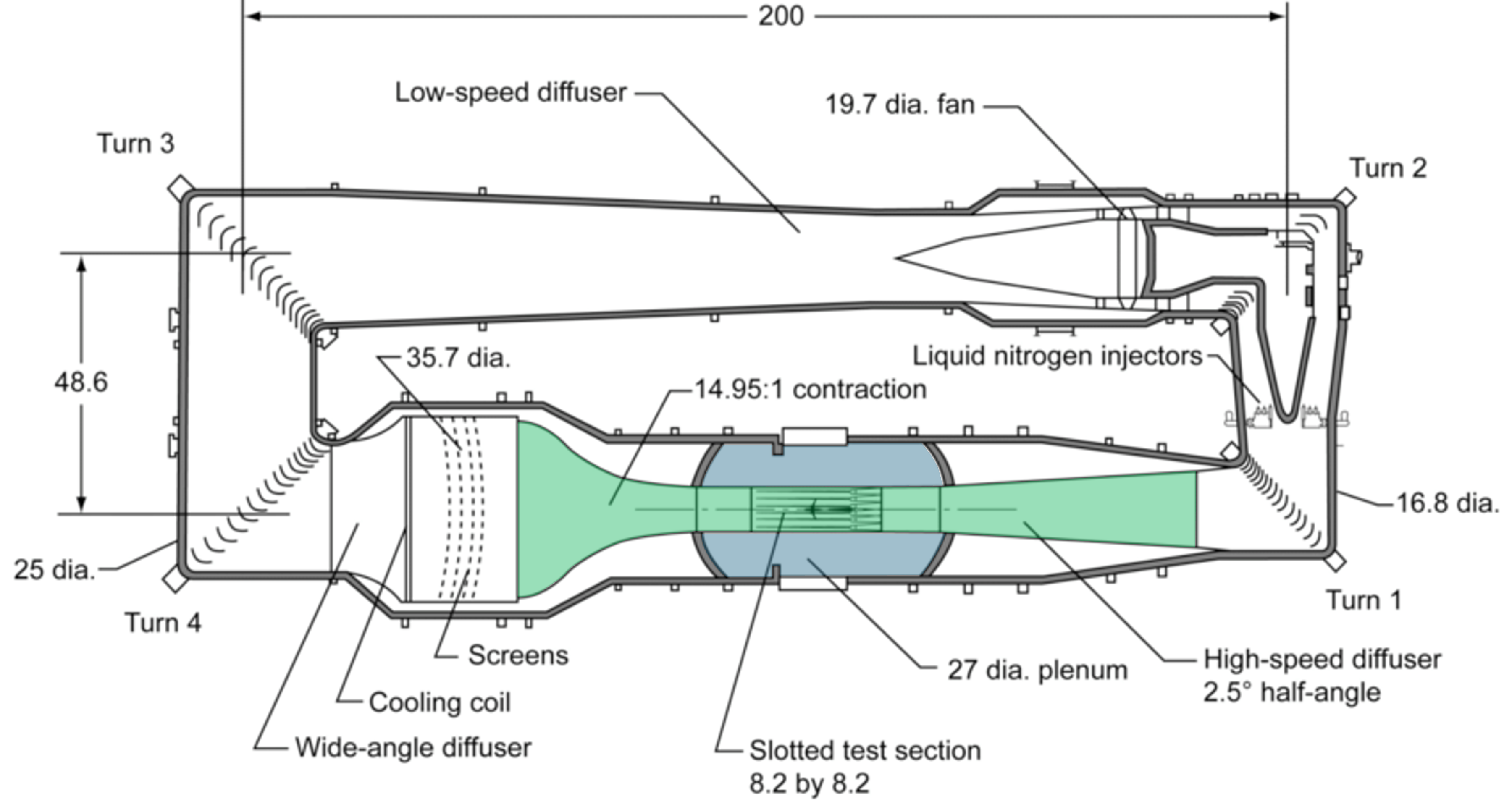
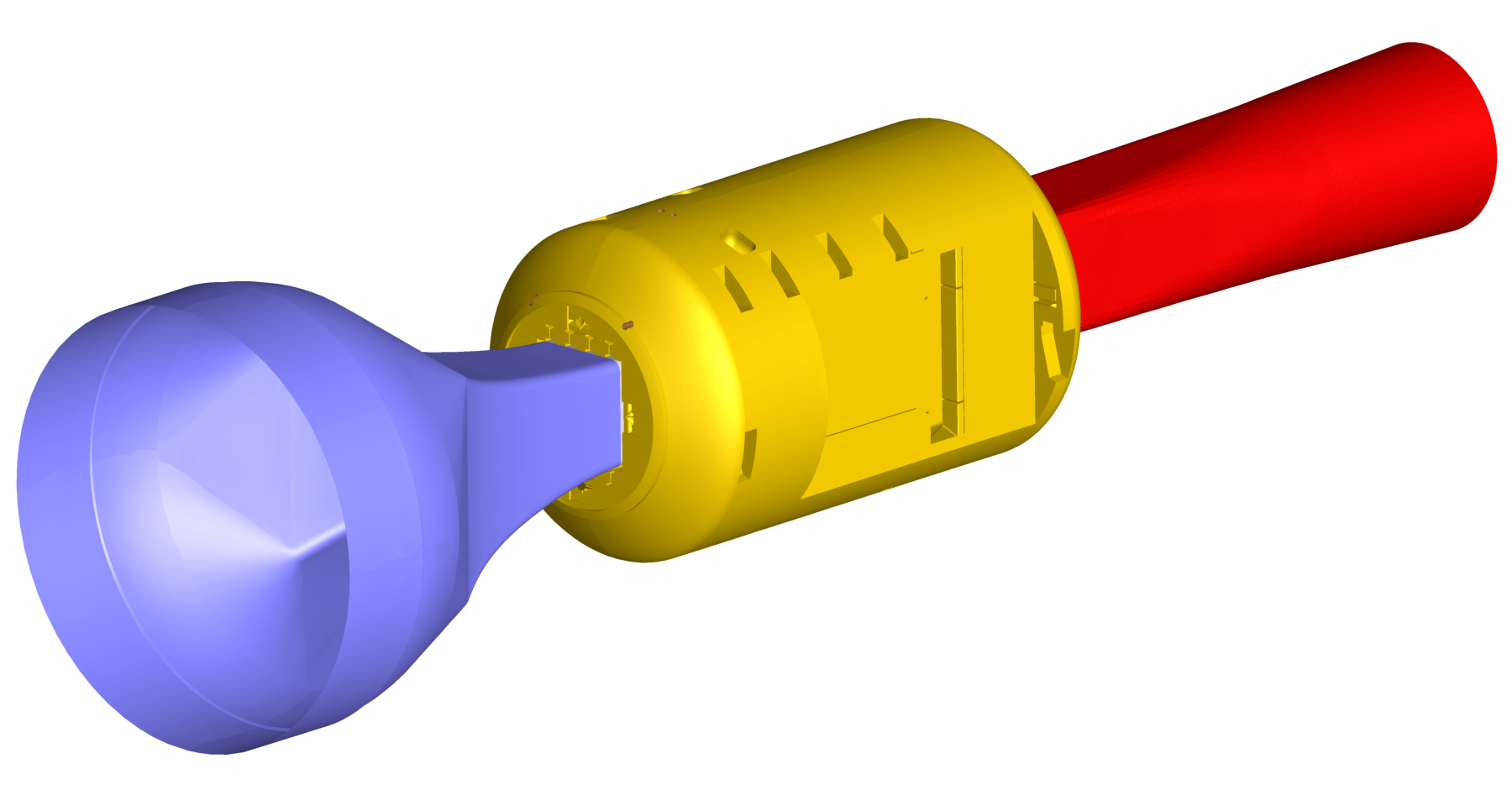
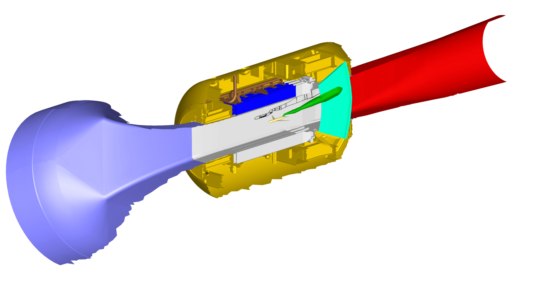
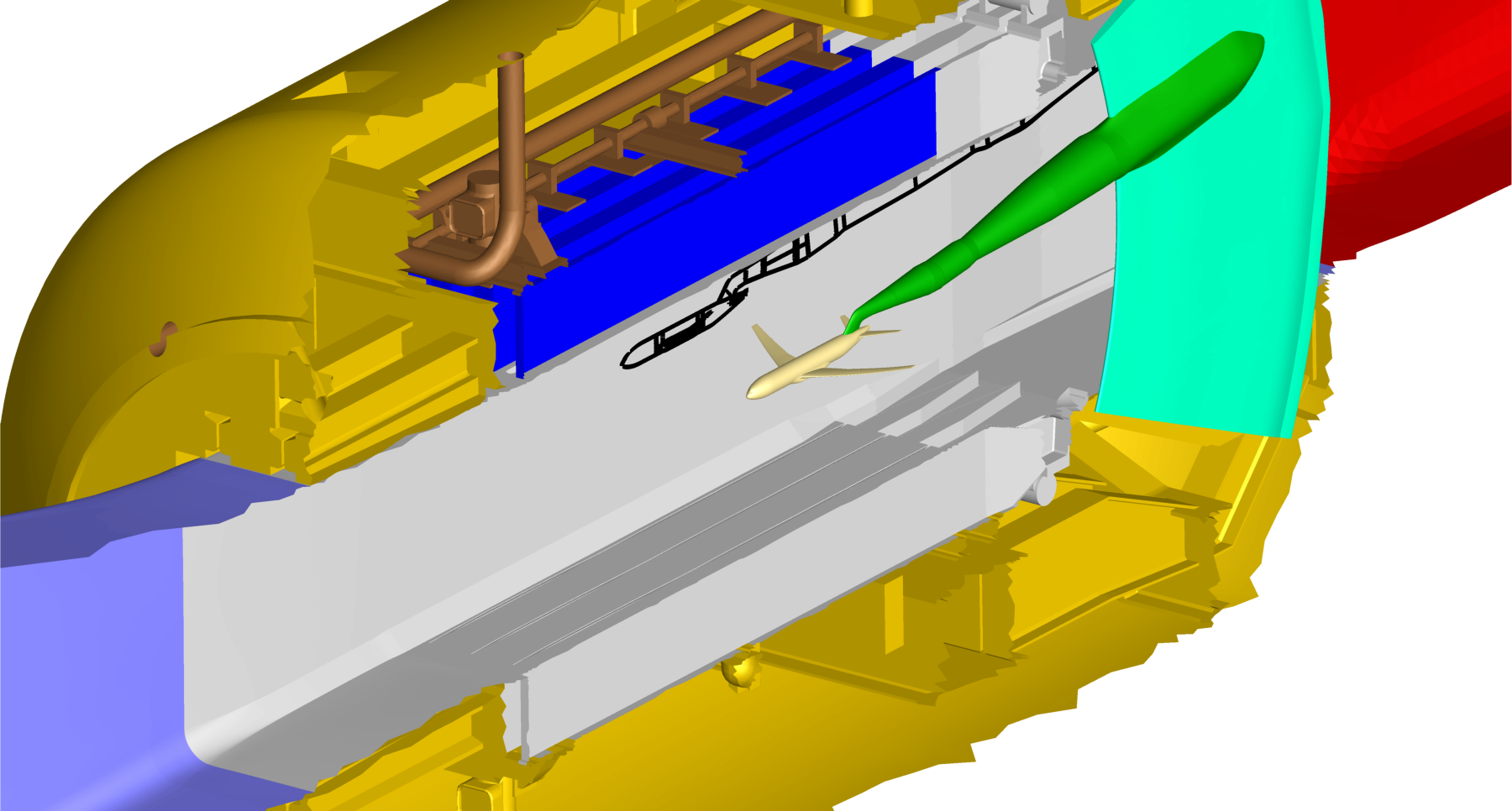
Circuit and released geometry
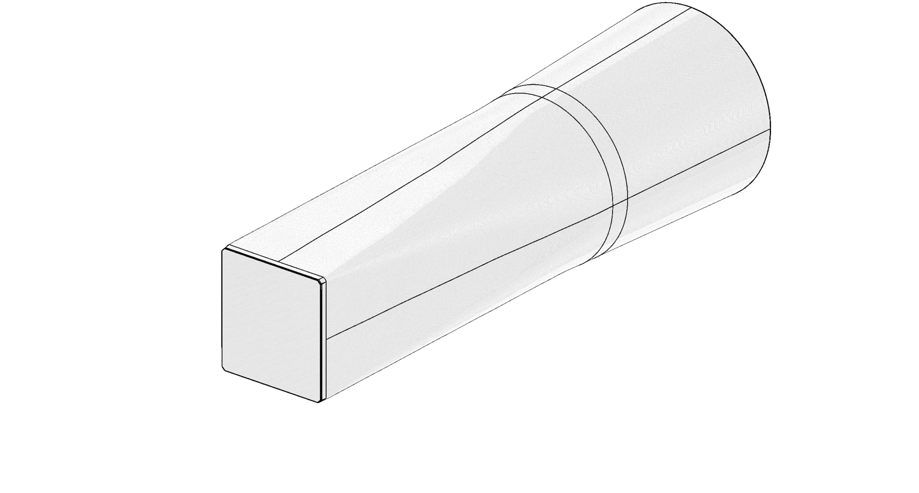
NTF_Additional_Obstructions_2023_10_02
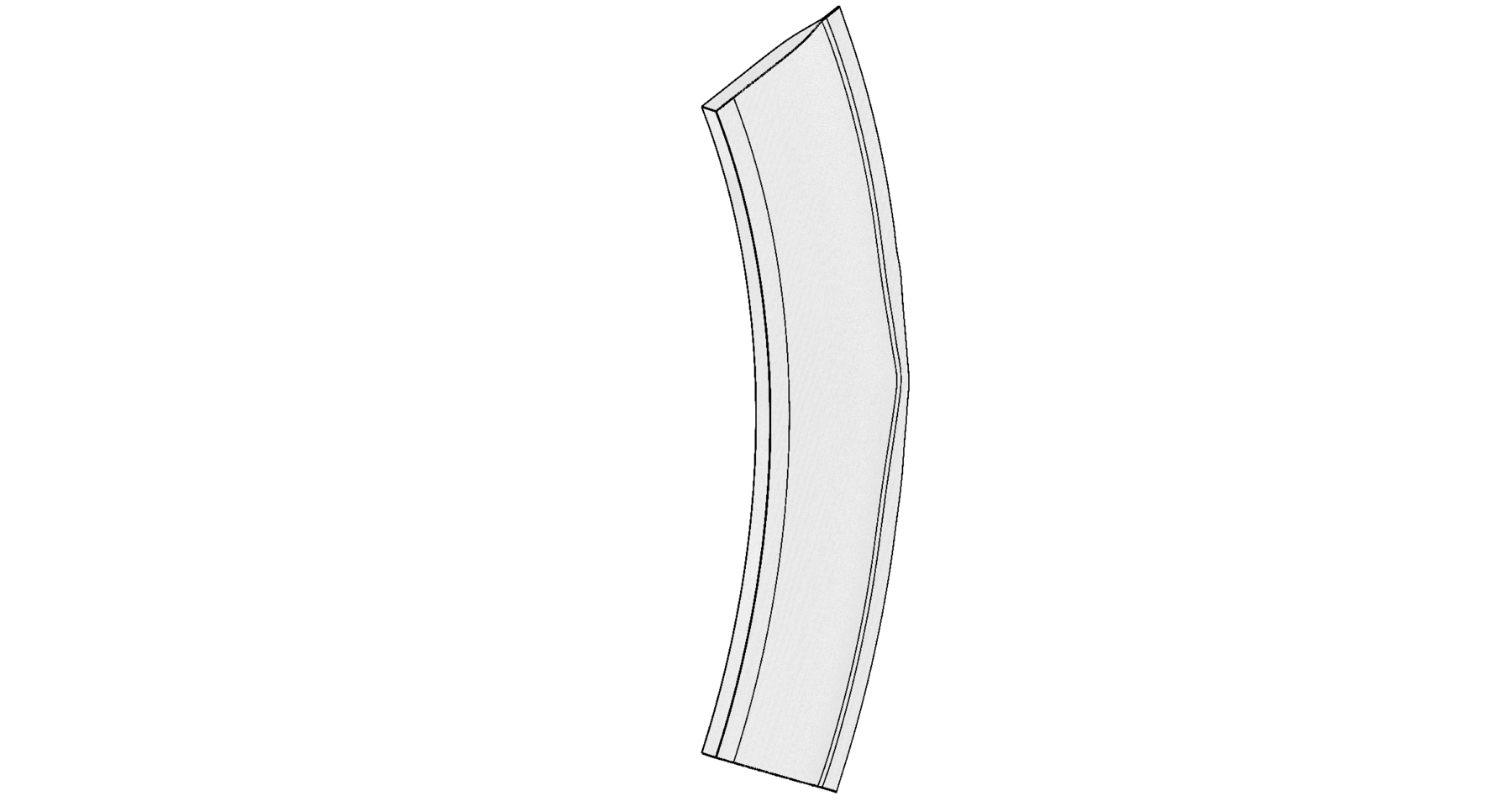
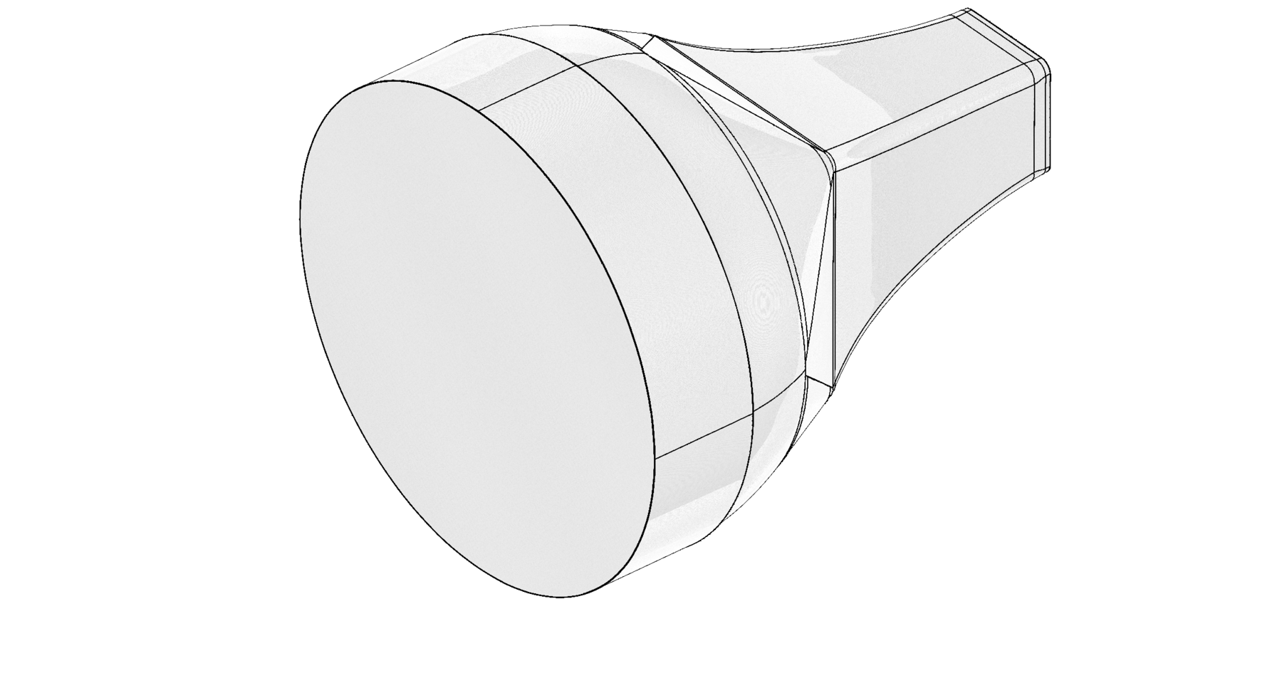
NTF_arc_sector_aft_fixed
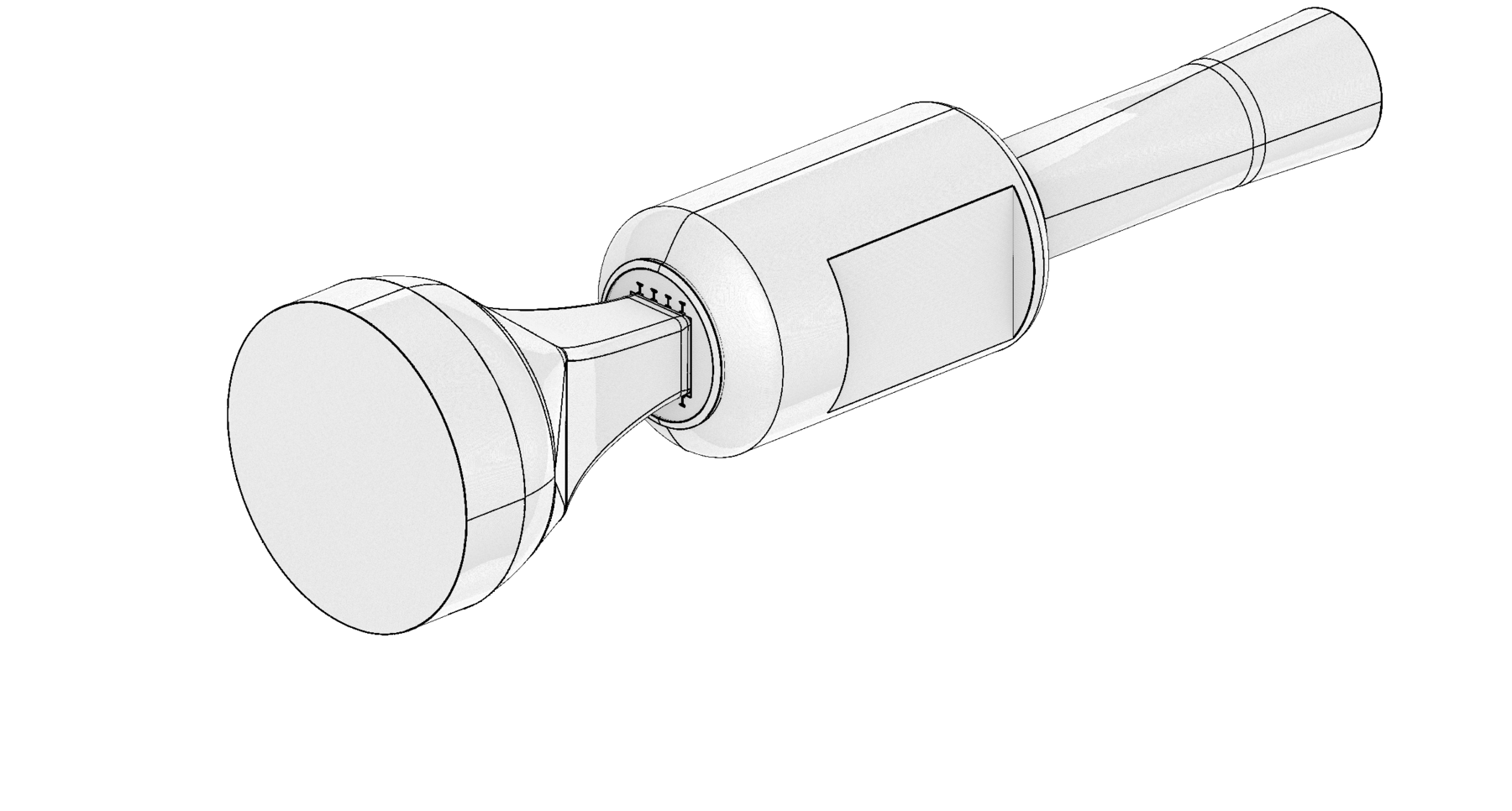
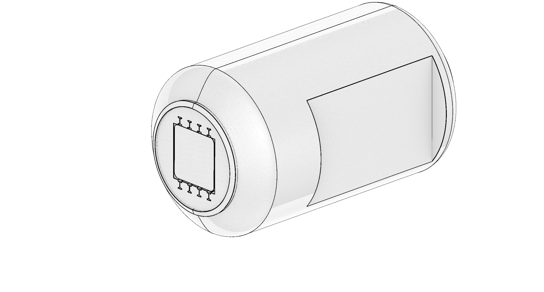
NTF_Arc_Sector_CameraPod_2023_10_02
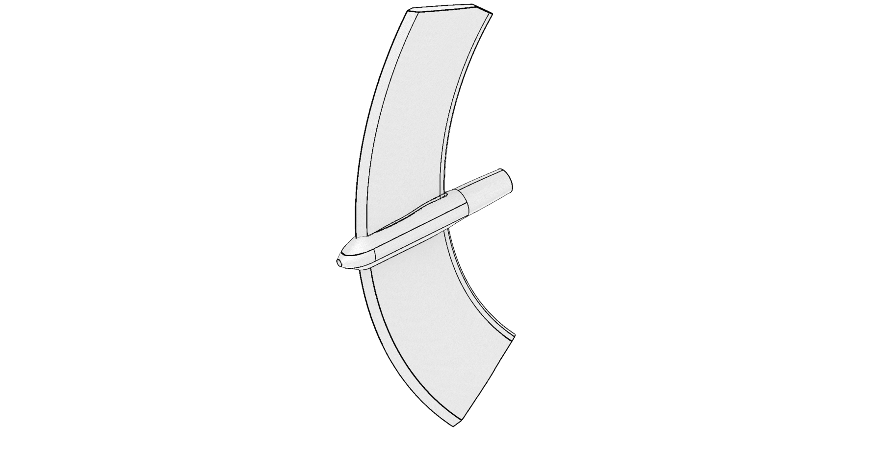
NTF_arc_sector_fwd_rotational_0deg

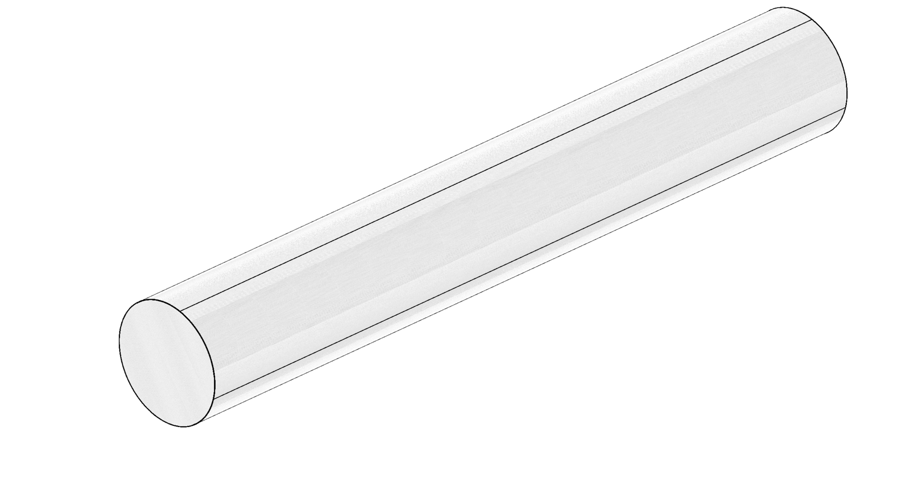
NTF_Arc_Sector_Rotational_Axis_Cylinder_2023_10_02
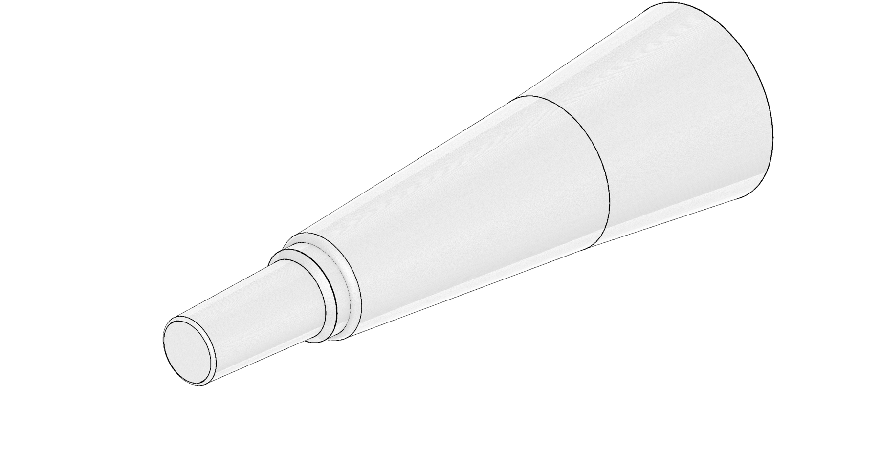
NTF_Arc_Sector_Straight_Sting_0deg_2023_10_02
NTF_Contraction_TestSection_Diffusor_2023_10_02
NTF_Diffusor_2023_10_02
NTF_Diffusor_Constant_Cross_Section_Extension_2023_10_02
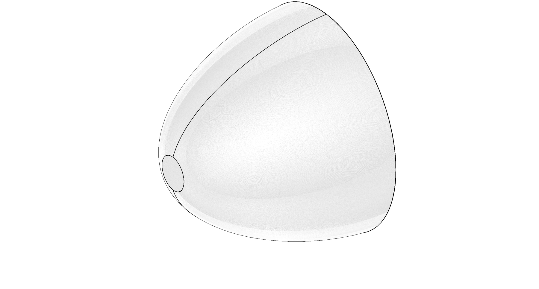
NTF_Inlet_Contraction_2023_10_02
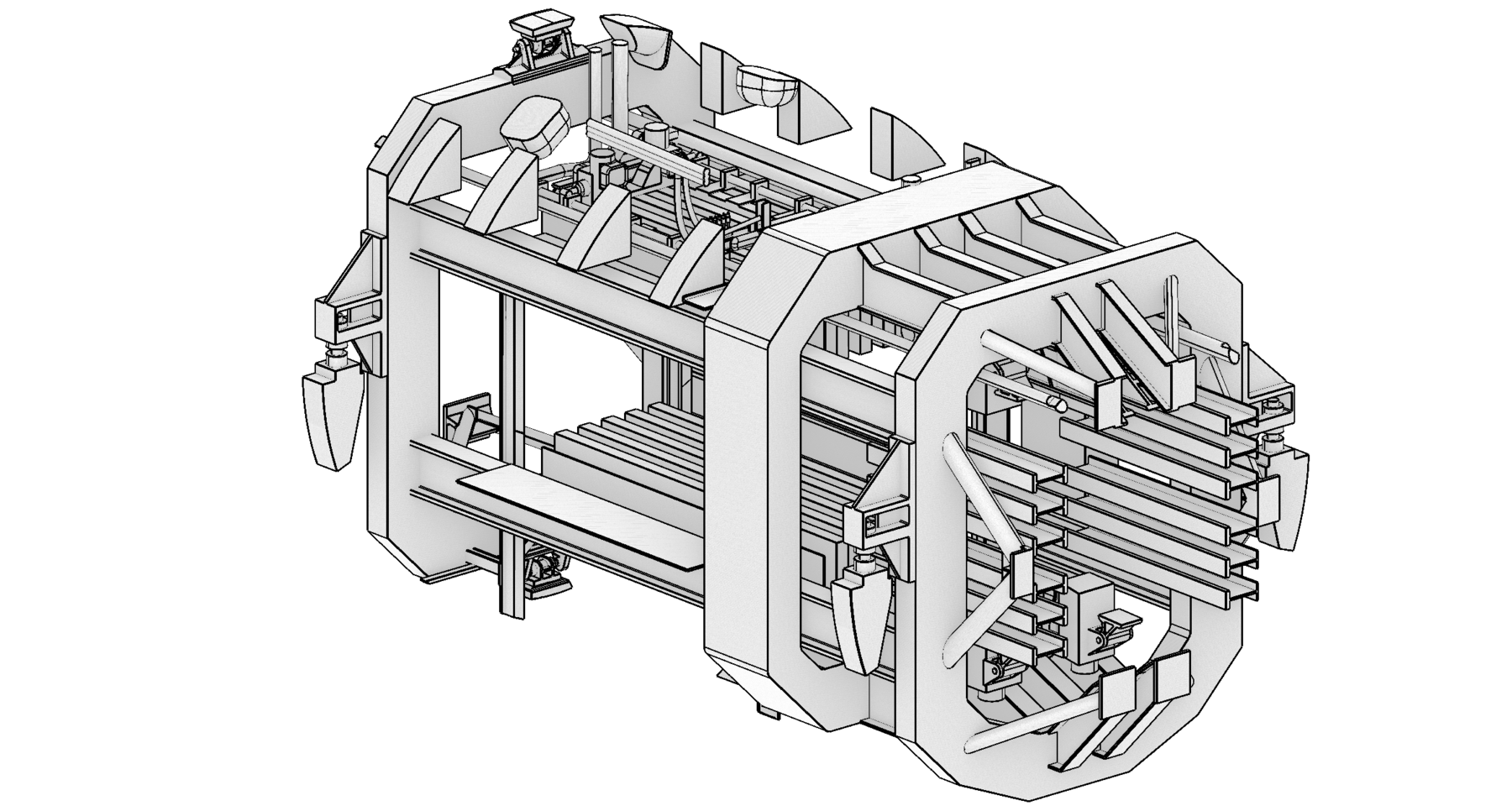
NTF_TestSection_Baseline_in_Plenum_2023_10_02
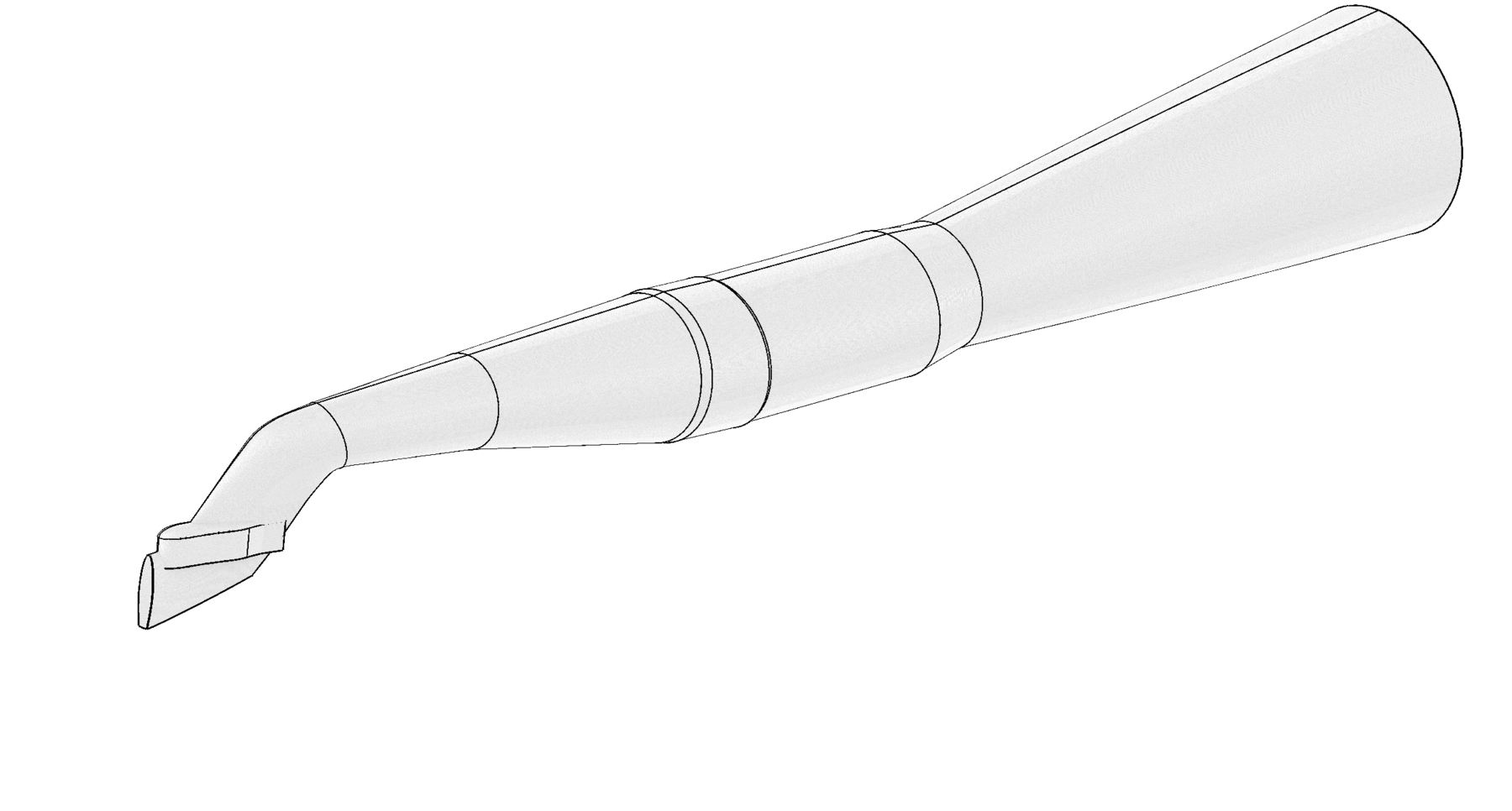
NTF_USS_Sting_noRotation_2024_08_15
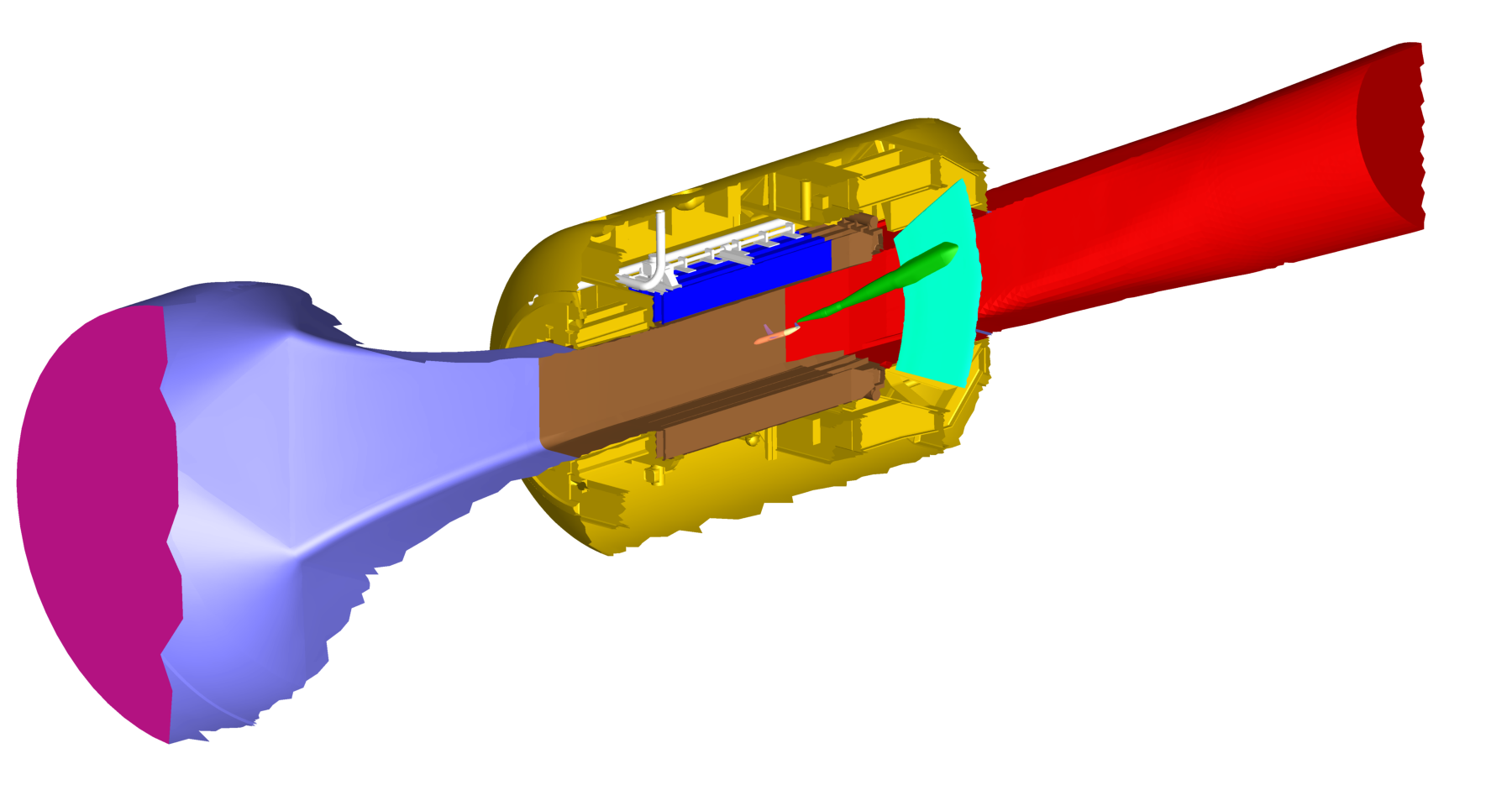
All parts with unique coloring
Isometric View 1
Isometric View 2
Isometric View 3
Isometric View 4
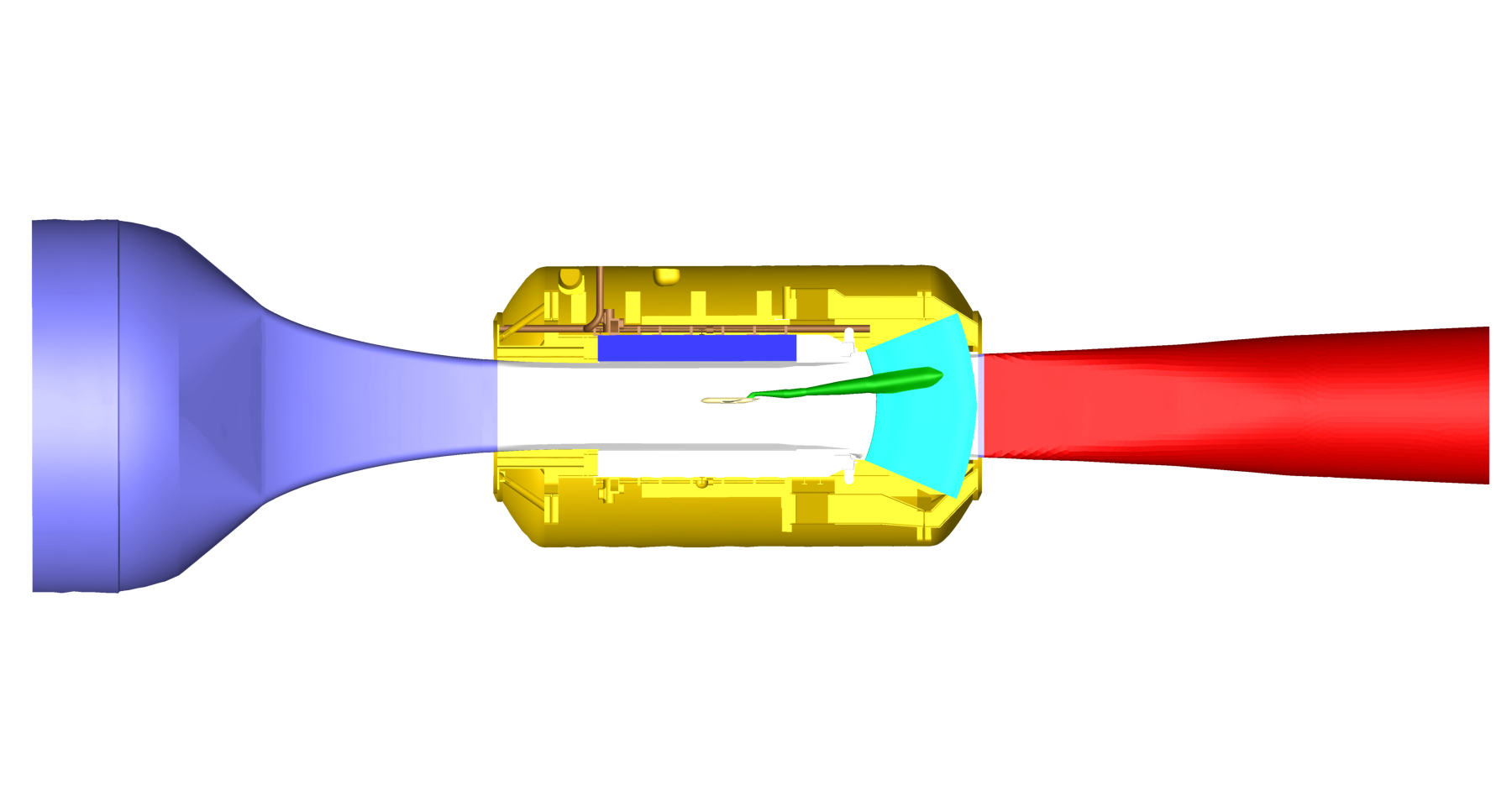
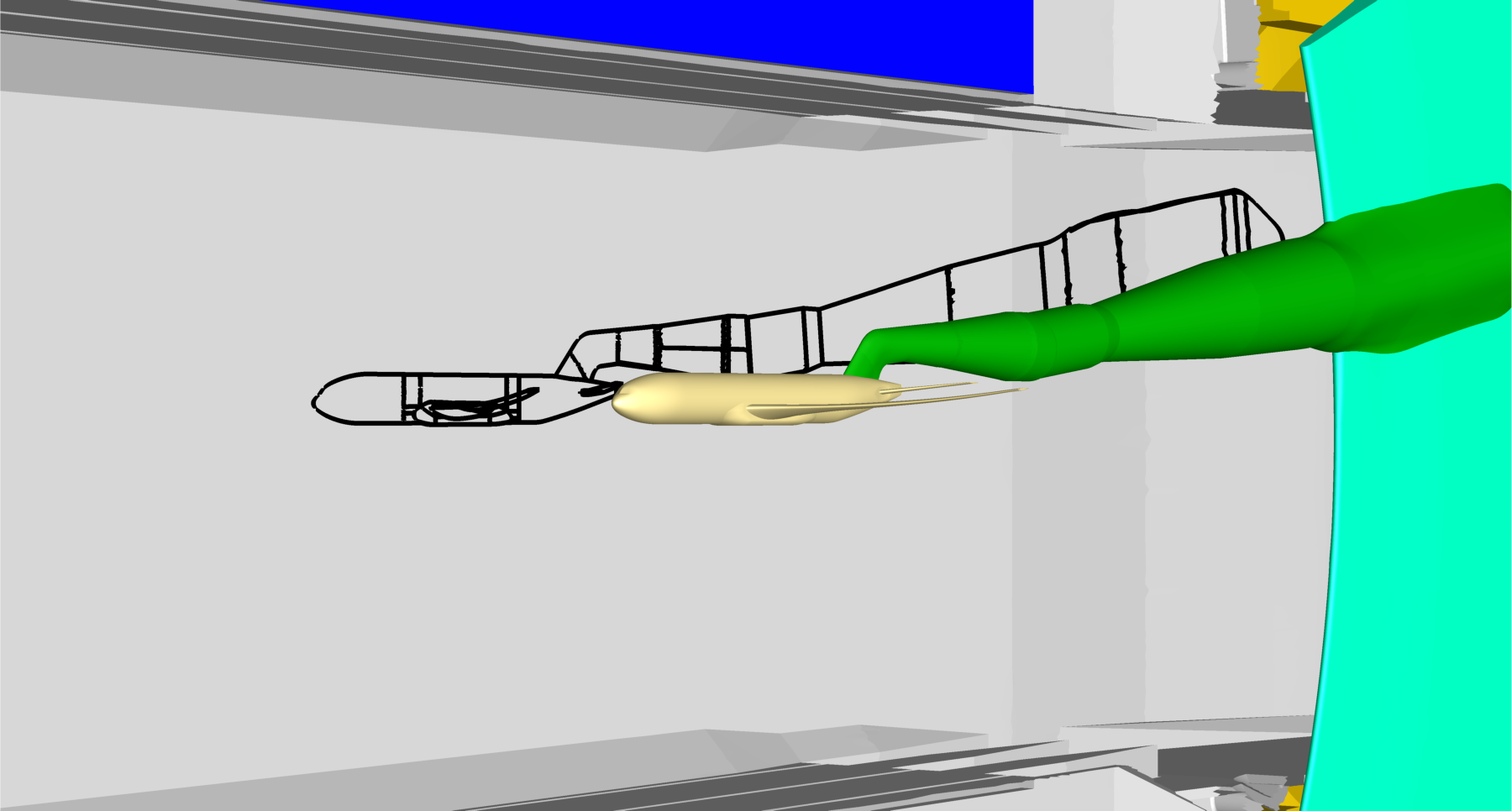
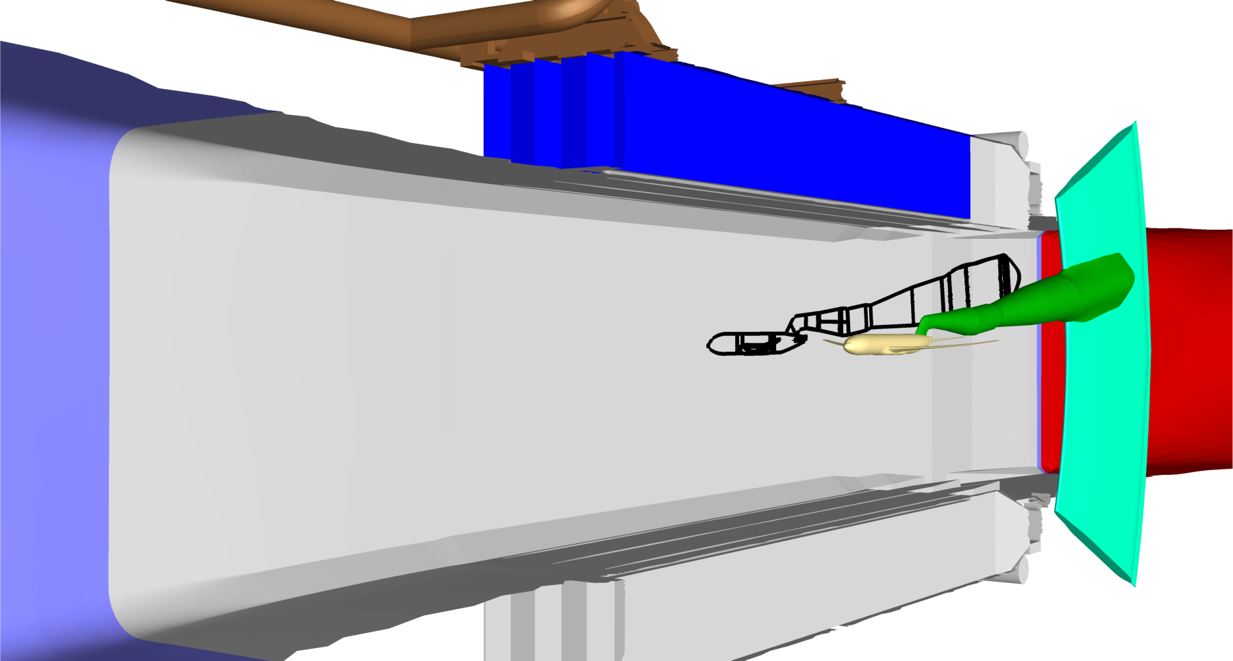
Side View 1
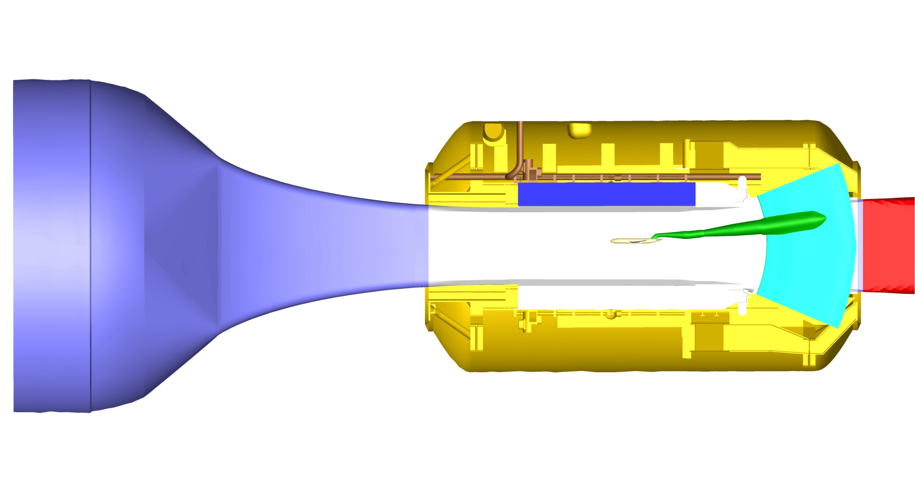
Side View 2
Side View 3
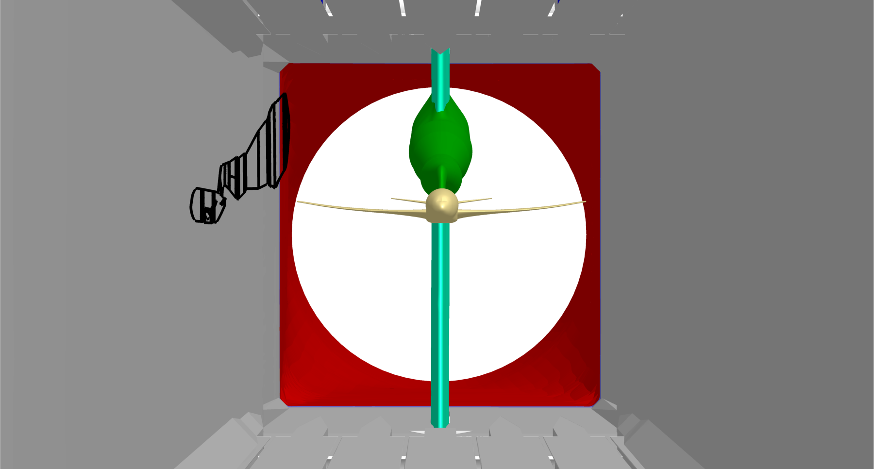
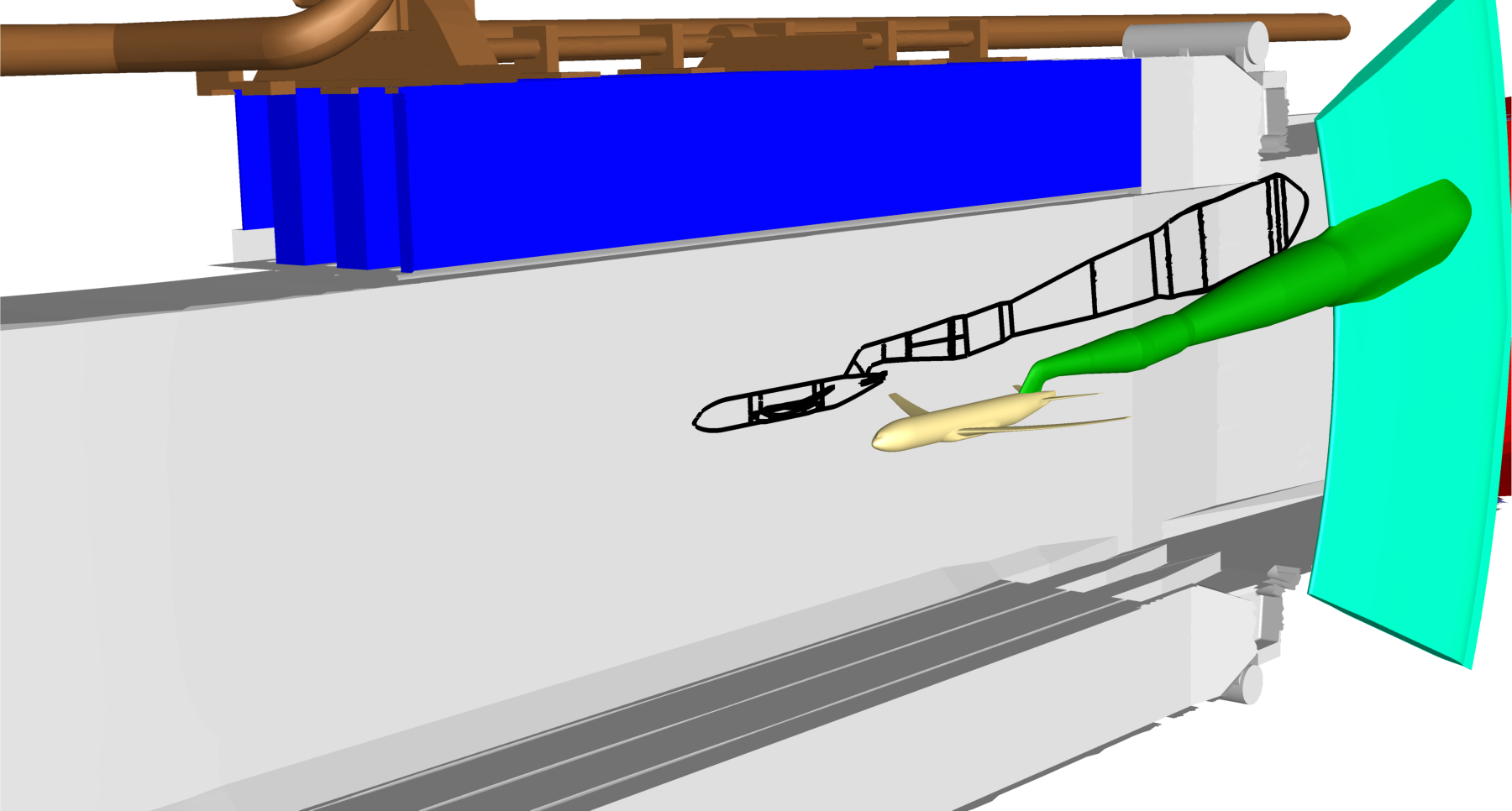
Interior View 1
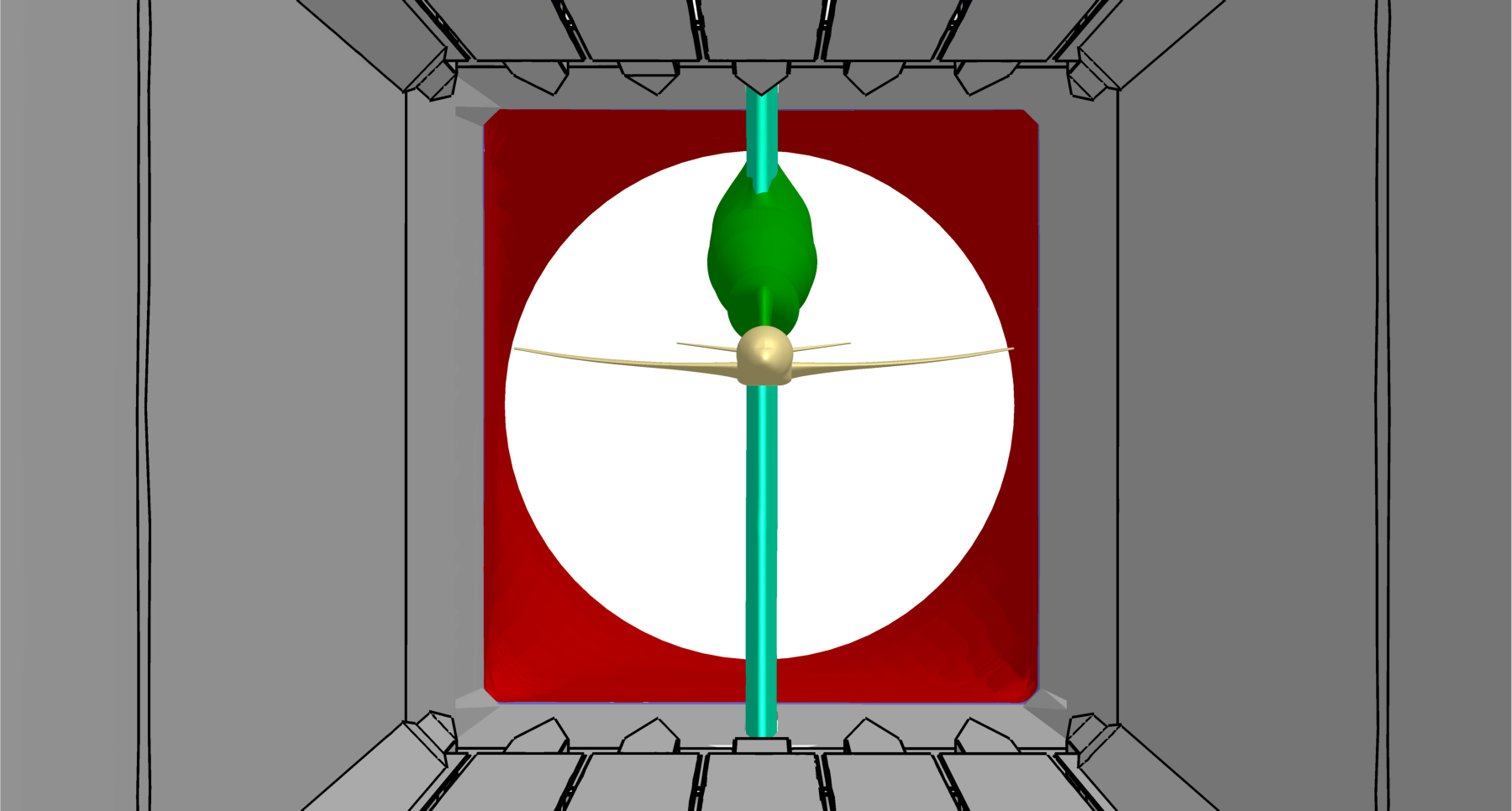
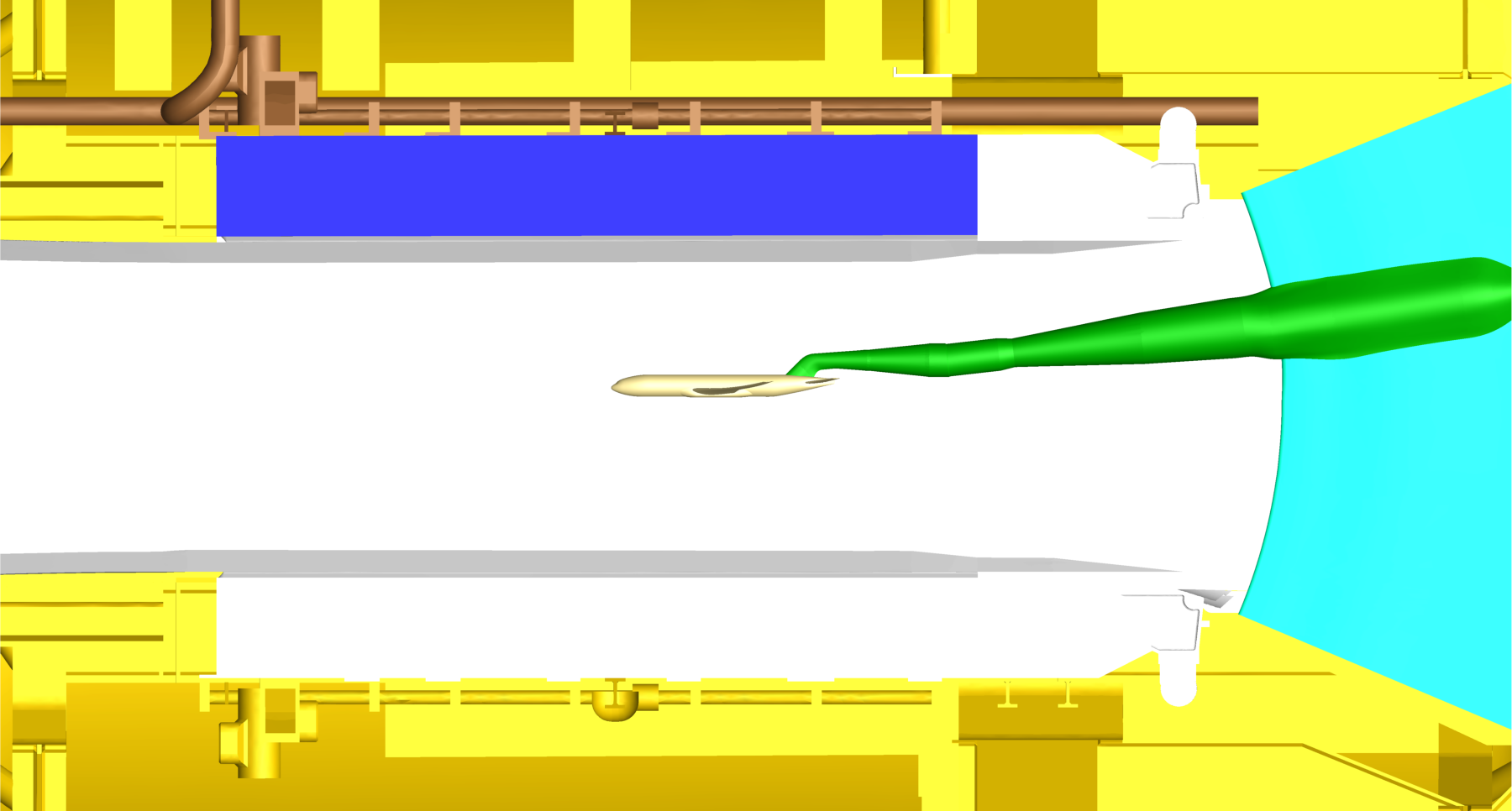
Interior View 2
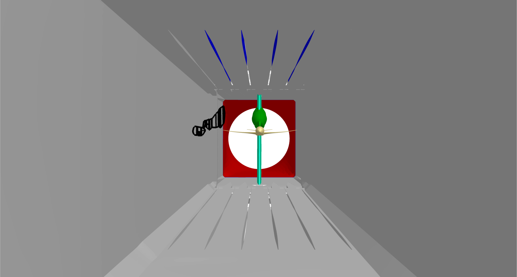
Interior View 3
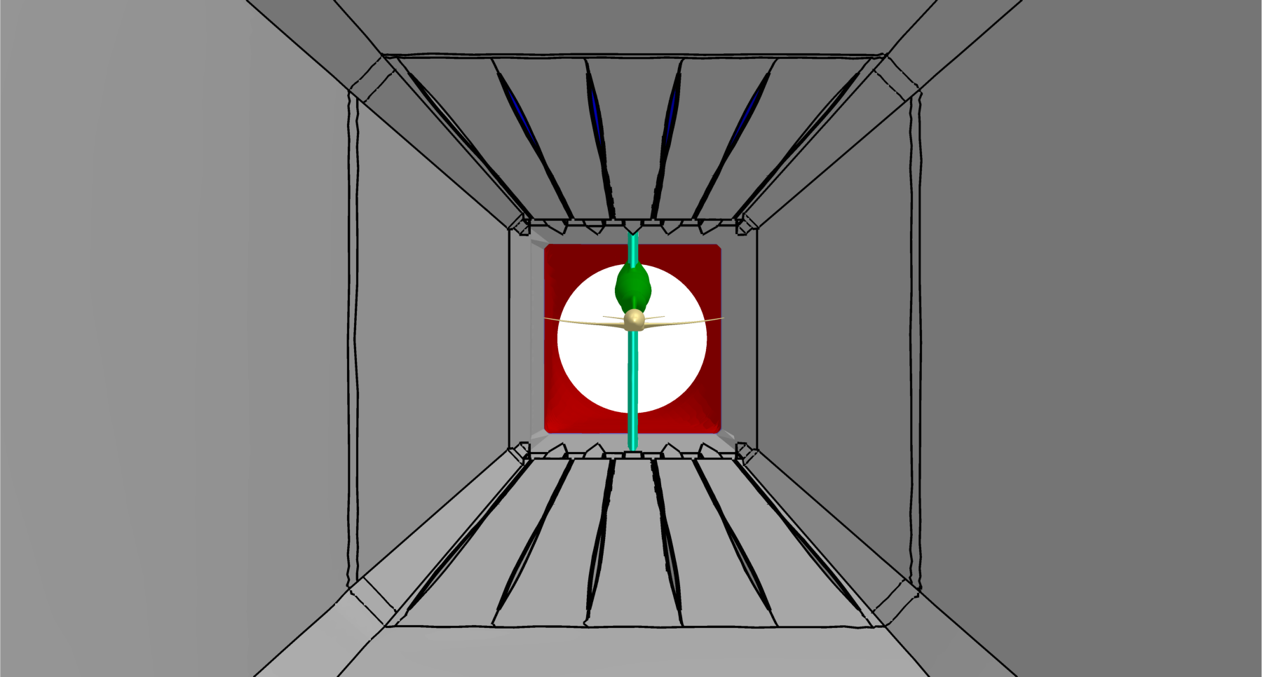
Interior View 4
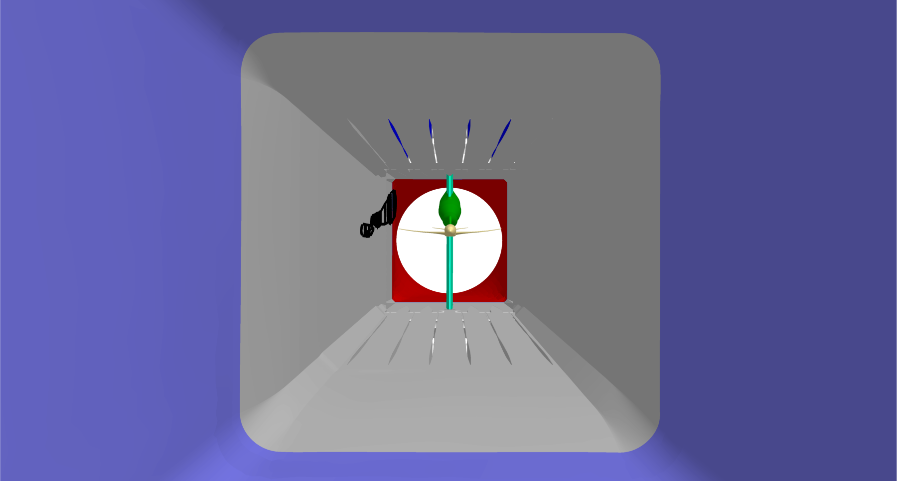
Interior View 5
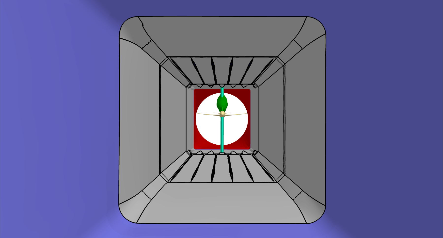
Interior View 6
Interior View 7
Interior View 8